Screwdriver operated spherical valve with nickel plated brass body and chromium plated brass ball. Compression connections are for use with copper pipes (manufactured to EN 1057). Maximum working pressure 10.0 bar. Maximum operating temperature 85°C.
Range of in-line spherical valves with a nickel-plated brass or DZR brass body, chromium plated brass or chromium plated DZR brass or stainless-steel ball and PTFE seats (see model for details). The products can be supplied with the following operating members: 1601 and 2045 ranges: single lever, single lever with extension stem kit, single lever with lockable handle or butterfly operating members. 1046 range: short black lever or screwdriver operated. The 11-1046 (1046) and 11-1015 (2045) ranges are for use with copper pipe (manufactured to EN1057). Maximum working pressures: 1046 and 2045 range: 25.0 bar. 1601 range: 40.0 bar. Maximum operating temperature 85°C.
Range of press fit spherical valves with brass and chrome plated brass bodies. For use with copper pipe to BS EN 1057. Maximum working pressure 16.0 Bar Maximum operating temperature 85 °C.
Range of spherical valves with nickel plated brass bodies, brass ball and PTFE seats. Valves with compression connections are for use with copper pipe (manufactured to EN1057). Maximum working pressure 16.0 bar. Maximum operating temperature 85°C.
Range of inline plastic bodied ball valves with EPDM ‘O-rings and lever operated. For use with PVC-U pressure pipe in accordance with BS EN 1452 standard Maximum working pressure. Sizes 20mm – 63mm & 1/2" – 2”: 16.0 Bar Sizes 110mm & 2 1/2” – 4”: 10.0 Bar Cold water only
Range of hand wheel operated gate valves with blue epoxy coated ductile iron bodies, ductile iron wedge encapsulated in EPDM. Maximum working pressure 16.0 Bar Maximum operating temperature 65.0°C
Range of gate valves with brass bodies, brass wedge and PTFE gaskets. The valves incorporate a hand wheel operating member. Maximum working pressure 20.0 bar. Maximum operating temperature 85°C.
Range of gate valves with bronze bodies, bronze wedge and PTFE gaskets. The valves incorporate a hand wheel operating member. Maximum working pressure 20.0 bar. Maximum operating temperature 85°C.
Range of 2, 3 ,4 or 5 way manifolds incorporating brass bodies, stop valves and EPDM O-rings, to be used with copper pipe to BS EN1057. Maximum working pressure 10.0 bar. Maximum operating temperature 85°C.
Range of screw down stop valves incorporating brass or bronze bodies and EPDM gaskets. Valves with compression connections are for use with copper pipe (manufactured to EN1057). Maximum working pressure 16.0 bar. Maximum operating temperature 80°C.
Monobloc manifold containing an in-line pressure reducing valve (Adjustment Range between 2.7 and 3.3 bar, but factory pre-set at 3 bar) and a pre-set expansion relief valve (pre-set pressure 6 bar) housed in a DZR brass body with an EPDM rubber diaphragm. The product incorporates also a check valve cartridge, verified by test (suitable for backflow protection against Fluid Category 2). Inlets and outlets have compression connections, for use with copper pipe to EN1057. Maximum working pressure 12 bar. Maximum operating temperature 80°C.
Range of inlet control groups with a DZR brass body, consisting of a pressure reducing valve and pressure relief valve set to 6bar. The outlet incorporates a single check valve cartridge verified by test (suitable for backflow protection against Fluid Category 2. Pressure reducing range 1 bar to 6 bar Maximum working pressure 10 Bar Maximum operating temperature 85°C
Range of double regulating valves incorporating bronze bodies, brass disc face (½” - ¾” models) or PTFE (1” - 2” models), PTFE plate and NBR ‘O’-rings. Maximum working pressure 25.0 bar. Maximum operating temperature 100°C.
Range of scale inhibitors with chrome plated copper bodies for use with copper pipe (manufactured to EN1057). Maximum working pressure 10.0 bar. Cold water use only.
'FGB15A -White, FGB15A -21364A Grey & FGB15A -21404A Grey'. ISOPOL modified, white or grey coloured brush Gelcoats. Apply as per manufacturer's TDS dated '04/11/2022'. Cure for 120 minutes@18°C. For use with water up to 23°C. This material is only approved for the mixing & curing conditions that appear on the approval. If the mix and/or cure conditions are varied from those specified on the approval then the material is not covered by the scope of the approval.
'Polyglass VEF'. Factory applied, two-part, off-white coloured, vinyl ester coating. Mix parts A & B in a 98:2 mass ratio and apply as per manufacturer's instructions '2/23' last reviewed July 2020. Cure for 7 days@21°C. For use with water up to 23°C. This material is only approved for the mixing & curing conditions that appear on the approval. If the mix and/or cure conditions are varied from those specified on the approval then the material is not covered by the scope of the approval.
‘Nitcote CM 210’. Site applied, two-part, grey coloured (once applied), Cementitious Waterproofing coating. Mix ‘CM 210 white’ liquid polymer and ‘CM 210 grey’ powder in a 1:3.6 weight ratio and apply two coats as per manufacturer's TDS 'UAE/0210/23/Z-1'. Cure Coat 1 for 3 hours@35°C and Coat 2 for 21 days@23°C. For use with water up to 65°C. This material is only approved for the mixing & curing conditions that appear on the approval. If the mix and/or cure conditions are varied from those specified on the approval then the material is not covered by the scope of the approval.
'TECHNYL ® SAFE A 219WFC V30 BK’ (black coloured) & ‘TECHNYL ® SAFE A 219WFC V30 NC’ (natural, appears off-white). Injection moulded, glass fibre reinforced polyamide 6.6 materials. For use with water up to 85°C.
'Seal Ring T11/T21'. Grey coloured, extruded PE seal ring. For use with water up to 85°C.
'3P764921 Pipe Spacer'. White coloured (opaque), injection moulded PP Pipe Spacer. For use with water up to 85°C.
‘Udel P-3500 NT LCD, GF-110 NT, GF-120 NT, GF-121 NT, P-1700 NT 11 MR, P-1700 NT 11, GF-121 NT ECHO RP & P-3500 NT LCD ECHO RP’ (all beige translucent). ‘Udel P-1700 Grey 8057’ (grey coloured). ‘Udel P-1700 BK 937, P-1700 BK 937 MR, GF-120 BK 937, GF-121 BK 937, GF-121 BK 937 ECHO RP, GF-120 BK 937 ECHO RP & P-1700 BK937 ECHO RP’ (all black coloured). ‘Udel P-1700 WH 7407’ (white coloured). Injection moulded, polysulphone materials. For use with water up to 85°C.
Range of floor standing, single hole, single outlet (fixed) combination tap assemblies, (brass bodies - various finishes), incorporating a ceramic cartridge headwork with a single lever operating member and a manual diverter to a shower outlet. The spout outlet incorporates a plastic aerator. Maximum working pressure 5 Bar Maximum operating temperature 65.0°C
Range of deck mounted, single hole, single outlet (fixed) electronically controlled tap assemblies (chrome plated stainless steel bodies). The flow is controlled by a solenoid valve that is activated via an infrared sensor, and the spout outlets incorporate plastic aerators. Maximum working pressure 8.0 Bar Maximum operating temperature 65.0°C
Range of single hole, single outlet (fixed) combination tap assemblies (chrome plated brass). Flow is controlled by a solenoid valve activated via an infra-red sensor. The spout outlets incorporate plastic aerators. Maximum working pressure:8.0 Bar Maximum operating temperature:65 °C
Single hole, single outlet (fixed) electronically controlled tap assemblies (chromium plated brass), flow is controlled by a solenoid valve, activated via an infra-red sensor. The product is supplied with a combined TPE washer and stainless-steel strainer to be installed on the inlet to the solenoid. The spout outlet incorporates a plastic flow straightener. Maximum working pressure 8.0 bar. Maximum operating temperature 65°C.
Range of bottom and side entry BS1212-4 (2016) compact type float operated inlet valves, for WC flushing cisterns with plastic bodies and adjustable floats and a plastic flow regulator at the inlet. Maximum operating pressure: 10 bar. Maximum operating temperature: 23°C.
Bottom entry BS1212-4 (2016) compact type float operated inlet valve for WC flushing cisterns with a plastic body and a plastic flow regulator at the inlet. Maximum working pressure 10.0 Bar Cold water use only
Concealed WC dual flushing cisterns with a vertical BS 1212-4(2016) float operated inlet valve providing a Type AG air gap arrangement and a dual flush outlet valve. The flush volume is operated by a two-push button assembly. The product also incorporates a servicing valve and flexible hose on the inlet supply. Maximum working pressure 10 Bar, cold water use only.
Concealed WC dual flushing cistern with a bottom entry BS 1212 - 4(2016) float operated inlet valve providing a Type AG air gap arrangement and a dual flush outlet valve. The flush volume is operated by a two-push button assembly for a 6 or 3 litre flush volume. Maximum working pressure 10.0 bar, cold water use only.
Low Level WC suites incorporating a frame mounted ceramic pan that is fitted with a washing & drying arrangement which is fed via a type `AB` airgap (verified by test - suitable for backflow protection against fluid category 5). The cistern incorporates a side entry BS1212/4 float operated inlet valve and provides a type `AB` air gap. The drop type flush valve provides a single flush of 6 litres and is operated by elbow push button levers that are designed into the front of the cistern cover. Maximum working pressure 10.0 bar. Cold water use only
Range of single hole, single outlet (fixed) combination tap assemblies (chrome plated brass bodies). Flow is controlled by solenoid valves activated via an infra-red sensor and the temperature is controlled independently via single lever. The spout outlets incorporate plastic aerators. Maximum working pressure 8 Bar. Maximum operating temperature 65°C.
Range of T type thermostatic mixing valves with chrome plated DZR brass bodies. Compression and push-fit models for use with copper pipe manufactured to EN1057. Models 37.20122.015.CP,37.20122.022.CP, 37.21122.015.CP, 37.21122.022.CP, 37.21222.015.CP, 37.21222.022.CP, 37.20162.015.CP, 37.20162.022.CP have isolation valves and strainers on the inlet. Maximum working pressure 10.0 Bar. Maximum operating temperature 85.0°C.
Range of non-verifiable single check valve assemblies with DZR brass bodies. Maximum operating pressure 10.0 bar. Maximum operating temperatures: 430357-003, 430357-004 and 430357-006 models: 85°C, 430357-008, 430357-010, 430357-011 and 430357-012 models: 65°C.
| Product Identification | Surface Finish / Colour | Dimension | Max Working Pressure (bar) | Max Operating Temp (°C) | Marking | Marking location | All metals in the water pathway are on the 4msi positive list | Headwork for Flow Control | Spout Outlet | Includes |
|---|---|---|---|---|---|---|---|---|---|---|
| 30 122 100 | NA | NA | 16 | 70 | HG | on the body | Yes | Ceramic cartridge | Not Applicable | |
| 30 122 101 | NA | NA | 16 | 70 | HG | on the body | Yes | Ceramic cartridge | Not Applicable | |
| 30 579 600 | NA | NA | 16 | 70 | HG | on the body | Yes | Ceramic cartridge | Not Applicable | |
| 30 333 001 | NA | NA | 16 | 70 | HG | on the body | Yes | Ceramic cartridge | Not Applicable | |
| 30 746 700 | NA | NA | 16 | 70 | HG | on the body | Yes | Ceramic cartridge | Not Applicable | |
| 30 746 702 | NA | NA | 16 | 70 | HG | on the body | Yes | Ceramic cartridge | Not Applicable |
30 122 100 - Diameter= 25,4mm 30 122 101 - Diameter= 25,4mm 30 333 001 - Diameter= 25,4mm 30 746 700 - Diameter= 25,4mm 30 746 702 - Diameter= 25,4mm 30 579 600 - Diameter= 25,4mm
| Product Identification | Surface Finish / Colour | Dimension | Max Working Pressure (bar) | Max Operating Temp (°C) | Marking | Marking location | All metals in the water pathway are on the 4msi positive list | Headwork for Flow Control | Spout Outlet | Includes |
|---|---|---|---|---|---|---|---|---|---|---|
| 501102 | Chrome | 1/2" BSP | 5 | 60 | KINEN | on handle | No | Ceramic cartridge | Aerator | Inlet Hoses |
| 501101 | Chrome | 1/2" BSP | 5 | 60 | KINEN | on handle | No | Ceramic cartridge | Aerator | Inlet Hoses |
| 5591103 | Chrome | 1/2" BSP | 12 | 60 | KINEN | on handle | No | Ceramic cartridge | Aerator | Inlet Hoses |
| 5591101 | Chrome | 1/2" BSP | 12 | 60 | KINEN | on handle | No | Ceramic cartridge | Aerator | Inlet Hoses |
| 5591104 | Chrome | 1/2" BSP | 12 | 60 | KINEN | on handle | No | Ceramic cartridge | Aerator | Inlet Hoses |
| 141102 | Chrome | 1/2" BSP | 12 | 60 | KINEN | on handle | No | Ceramic cartridge | Aerator | Inlet Hoses |
| 141101 | Chrome | 1/2" BSP | 12 | 60 | KINEN | on handle | No | Ceramic cartridge | Aerator | Inlet Hoses |
| 141104 | Chrome | 1/2" BSP | 12 | 60 | KINEN | on handle | No | Ceramic cartridge | Aerator | Inlet Hoses |
| Product Identification | Surface Finish / Colour | Dimension | Max Working Pressure (bar) | Max Operating Temp (°C) | Marking | Marking location | All metals in the water pathway are on the 4msi positive list | Headwork for Flow Control | Spout Outlet | Includes |
|---|---|---|---|---|---|---|---|---|---|---|
| 71 550 xx0 | G 3/8 | 10 | 60 | hansgrohe | on the handle | Yes | Ceramic cartridge | Aerator | Inlet Hoses | |
| 71 551 xx0 | G 3/8 | 10 | 60 | hansgrohe | on the handle | Yes | Ceramic cartridge | Aerator | Inlet Hoses | |
| 71 557 xx0 | G 3/8 | 10 | 60 | hansgrohe | on the handle | Yes | Ceramic cartridge | Aerator | Inlet Hoses | |
| 71 558 xx0 | G 3/8 | 10 | 60 | hansgrohe | on the handle | Yes | Ceramic cartridge | Aerator | Inlet Hoses | |
| 71 559 xx0 | G 3/8 | 10 | 60 | hansgrohe | on the handle | Yes | Ceramic cartridge | Aerator | Inlet Hoses | |
| 71 560 xx0 | G 3/8 | 10 | 60 | hansgrohe | on the handle | Yes | Ceramic cartridge | Aerator | Inlet Hoses | |
| 71 561 xx0 | G 3/8 | 10 | 60 | hansgrohe | on the handle | Yes | Ceramic cartridge | Aerator | Inlet Hoses | |
| 71 580 xx0 | G 3/8 | 10 | 60 | hansgrohe | on the handle | Yes | Ceramic cartridge | Aerator | Inlet Hoses | |
| 71 584 xx0 | G 3/8 | 10 | 60 | hansgrohe | on the handle | Yes | Ceramic cartridge | Aerator | Inlet Hoses | |
| 71 585 xx0 | G 3/8 | 10 | 60 | hansgrohe | on the handle | Yes | Ceramic cartridge | Aerator | Inlet Hoses | |
| 71 589 xx0 | G 3/8 | 10 | 60 | hansgrohe | on the handle | Yes | Ceramic cartridge | Aerator | Inlet Hoses | |
| 71 593 xx0 | G 3/8 | 10 | 60 | hansgrohe | on the handle | Yes | Ceramic cartridge | Aerator | Inlet Hoses | |
| 71 594 xx0 | G 3/8 | 10 | 60 | hansgrohe | on the handle | Yes | Ceramic cartridge | Aerator | Inlet Hoses | |
| 71 598 xx0 | G 3/8 | 10 | 60 | hansgrohe | on the handle | Yes | Ceramic cartridge | Aerator | Inlet Hoses | |
| 71 526 xx0 | G 3/8 | 10 | 60 | hansgrohe | on the handle | Yes | Ceramic cartridge | Aerator | Inlet Hoses | |
| 71 527 xx0 | G 3/8 | 10 | 60 | hansgrohe | on the handle | Yes | Ceramic cartridge | Aerator | Inlet Hoses | |
| 71 528 xx0 | G 3/8 | 10 | 60 | hansgrohe | on the handle | Yes | Ceramic cartridge | Aerator | Inlet Hoses | |
| 71 529 xx0 | G 3/8 | 10 | 60 | hansgrohe | on the handle | Yes | Ceramic cartridge | Aerator | Inlet Hoses |
Where xx0 denotes the surface finish. It will always be 3 digits, which can be any combination of numbers and/or letters, as examples: 000 = chrome optic finish, 800 = PVD stainless steel optic finish

| Product Identification | Surface Finish / Colour | Dimension | Max Working Pressure (bar) | Max Operating Temp (°C) | Marking | Marking location | All metals in the water pathway are on the 4msi positive list | Headwork for Flow Control | Spout Outlet | Includes |
|---|---|---|---|---|---|---|---|---|---|---|
| 10 003 xx0 | Where xx0 denotes the surface finish (which is a non-water contact part). It will always be 3 digits, which can be any combination of numbers and/or letters, as examples: 000 = chrome optic finish, 800 = PVD stainless steel optic finish | G 3/8 | 10 | 60 | AXOR | on the body | Yes | Ceramic cartridge | Aerator | Inlet Hoses |
| 10 001 xx0 | Where xx0 denotes the surface finish (which is a non-water contact part). It will always be 3 digits, which can be any combination of numbers and/or letters, as examples: 000 = chrome optic finish, 800 = PVD stainless steel optic finish | G 3/8 | 10 | 60 | AXOR | on the body | Yes | Ceramic cartridge | Aerator | Inlet Hoses |
| 10 007 xx0 | Where xx0 denotes the surface finish (which is a non-water contact part). It will always be 3 digits, which can be any combination of numbers and/or letters, as examples: 000 = chrome optic finish, 800 = PVD stainless steel optic finish | G 3/8 | 10 | 60 | AXOR | on the body | Yes | Ceramic cartridge | Aerator | Inlet Hoses |
| 10 102 xx0 | Where xx0 denotes the surface finish (which is a non-water contact part). It will always be 3 digits, which can be any combination of numbers and/or letters, as examples: 000 = chrome optic finish, 800 = PVD stainless steel optic finish | G 3/8 | 10 | 60 | AXOR | on the body | Yes | Ceramic cartridge | Aerator | Inlet Hoses |
| 10 103 xx0 | Where xx0 denotes the surface finish (which is a non-water contact part). It will always be 3 digits, which can be any combination of numbers and/or letters, as examples: 000 = chrome optic finish, 800 = PVD stainless steel optic finish | G 3/8 | 10 | 60 | AXOR | on the body | Yes | Ceramic cartridge | Aerator | Inlet Hoses |
Where xx0 denotes the surface finish (which is a non-water contact part). It will always be 3 digits, which can be any combination of numbers and/or letters, as examples: 000 = chrome optic finish, 800 = PVD stainless steel optic finish.
| Product Identification | Surface Finish / Colour | Dimension | Max Working Pressure (bar) | Max Operating Temp (°C) | Marking | Marking location | All metals in the water pathway are on the 4msi positive list | Headwork for Flow Control | Spout Outlet | Includes |
|---|---|---|---|---|---|---|---|---|---|---|
| 71 554 xx0 | Where xx0 denotes the surface finish (which is a non-water contact part). It will always be 3 digits, which can be any combination of numbers and/or letters, as examples: 000 = chrome optic finish, 800 = PVD stainless steel optic finish | G 3/8 | 10 | 60 | hansgrohe | on the body | Yes | Ceramic cartridge | Aerator | Inlet Hoses |
| 71 564 xx0 | Where xx0 denotes the surface finish (which is a non-water contact part). It will always be 3 digits, which can be any combination of numbers and/or letters, as examples: 000 = chrome optic finish, 800 = PVD stainless steel optic finish | G 3/8 | 10 | 60 | hansgrohe | on the body | Yes | Ceramic cartridge | Aerator | Inlet Hoses |
| 71 870 xx0 | Where xx0 denotes the surface finish (which is a non-water contact part). It will always be 3 digits, which can be any combination of numbers and/or letters, as examples: 000 = chrome optic finish, 800 = PVD stainless steel optic finish | G 3/8 | 10 | 60 | hansgrohe | on the body | Yes | Ceramic cartridge | Aerator | Inlet Hoses |
| 71 871 xx0 | Where xx0 denotes the surface finish (which is a non-water contact part). It will always be 3 digits, which can be any combination of numbers and/or letters, as examples: 000 = chrome optic finish, 800 = PVD stainless steel optic finish | G 3/8 | 10 | 60 | hansgrohe | on the body | Yes | Ceramic cartridge | Aerator | Inlet Hoses |
| 71 857 xx0 | Where xx0 denotes the surface finish (which is a non-water contact part). It will always be 3 digits, which can be any combination of numbers and/or letters, as examples: 000 = chrome optic finish, 800 = PVD stainless steel optic finish | G 3/8 | 10 | 60 | hansgrohe | on the body | Yes | Ceramic cartridge | Aerator | Inlet Hoses |
| 71 878 xx0 | Where xx0 denotes the surface finish (which is a non-water contact part). It will always be 3 digits, which can be any combination of numbers and/or letters, as examples: 000 = chrome optic finish, 800 = PVD stainless steel optic finish | G 3/8 | 10 | 60 | hansgrohe | on the body | Yes | Ceramic cartridge | Aerator | Inlet Hoses |
| Product Identification | Surface Finish / Colour | Dimension | Max Working Pressure (bar) | Max Operating Temp (°C) | Marking | Marking location | All metals in the water pathway are on the 4msi positive list | Headwork for Flow Control | Spout Outlet | Includes |
|---|---|---|---|---|---|---|---|---|---|---|
| SJS-WB100* ** | Various | BSP 1/2" (F) Captive nut | 10 | 60 | Kind | Handle | No | Ceramic cartridge | Aerator | Inlet Hoses, Interconnecting Hoses |
| SJS-WB200* ** | Various | BSP 1/2" (F) Captive nut | 10 | 60 | Kind | Handle | No | Ceramic cartridge | Aerator | Inlet Hoses, Interconnecting Hoses |
| SJS-WB101* ** | Various | BSP 1/2" (F) Captive nut | 10 | 60 | Kind | Handle | No | Ceramic cartridge | Aerator | Inlet Hoses, Interconnecting Hoses |
| JD-WB743* ** | Various | BSP 1/2" (F) Captive nut | 10 | 60 | Kind | Spout | No | Ceramic cartridge | Aerator | Inlet Hoses, Interconnecting Hoses |
The first * stands for the different handle A, B,C and D, if there is no handle, no first * ** represents different types of finishes as follows: C: Chrome NS: Nickel brushed RP: Red powder coated TS: Zr gold brushed RS: Rose gold brushed GS: Gold brushed GM: Gun metal brushed B: Electroplated matte black W: White CB: Matte black and chrome CW: White and chrome TG: Zr gold plated RG: Rose gold plated G: Gold plated GP: Gun metal plated BS: Gun gray brushed
Range of two hole, single outlet (fixed) combination tap assemblies (chromium plated brass). Models 91742, 805777 & 21775 incorporate a non-rising spindle headwork. Models 91742 & 805777 with dome type operating members Model 21775 with lever type operating members. Models 77174 & 805783 incorporate a quarter turn ceramic disc headwork with dome operating members. The fitting incorporates a manual diverter to the shower outlet The spout outlet incorporates a plastic flow straightener and the products are supplied with a shower hose, shower handset and metal back-nuts. Maximum working pressure 10.0 bar. Maximum operating temperature 70°C.
| Product Identification | Surface Finish / Colour | Dimension | Max Working Pressure (bar) | Max Operating Temp (°C) | Marking | Marking location | All metals in the water pathway are on the 4msi positive list | Headwork for Flow Control | Spout Outlet | Includes |
|---|---|---|---|---|---|---|---|---|---|---|
| J THBSMVO C | Chrome | G 3/4" (M) | 10 | 60 | Bristan | Handle | No | 1/4 Turn ceramic disk | Not Applicable | Flow Regulator Fitted |
| Product Identification | Surface Finish / Colour | Dimension | Max Working Pressure (bar) | Max Operating Temp (°C) | Marking | Marking location | All metals in the water pathway are on the 4msi positive list | Headwork for Flow Control | Spout Outlet | Includes |
|---|---|---|---|---|---|---|---|---|---|---|
| VAL2 PSNK C CD | Crome | 1/2" BSP (M) | 5 | 60 | Bristan | Handle | No | 1/4 Turn ceramic disk | Open Outlet |
Note - Both Products are the same, one is wall mounted, one is deck mounted.
| Product Identification | Surface Finish / Colour | Dimension | Max Working Pressure (bar) | Max Operating Temp (°C) | Marking | Marking location | All metals in the water pathway are on the 4msi positive list | Headwork for Flow Control | Spout Outlet | Includes |
|---|---|---|---|---|---|---|---|---|---|---|
| 2720065 | Chromed | BSP 1/2" (M) | 10 | 85 | MVI | Rear of body | No | Non-rising spindle | Flow Straightener | |
| 2720095 | Chromed | BSP 1/2" (M) | 10 | 85 | MVI | Rear of body | No | 1/4 Turn ceramic disk | Flow Straightener |
| Product Identification | Surface Finish / Colour | Dimension | Max Working Pressure (bar) | Max Operating Temp (°C) | Marking | Marking location | All metals in the water pathway are on the 4msi positive list | Headwork for Flow Control | Spout Outlet | Includes |
|---|---|---|---|---|---|---|---|---|---|---|
| JD-792* ** | Various | BSP 1/2" (F) | 10 | 60 | Kind | Handle, spout | No | 1/4 Turn ceramic disk | Aerator | |
| JD-742-2* ** | Various | BSP 1/2" (F) | 10 | 60 | Kind | Spout | No | 1/4 Turn ceramic disk | Aerator | |
| JD-702* ** | Various | BSP 1/2" (F) | 10 | 60 | Kind | Spout | No | 1/4 Turn ceramic disk | Aerator | |
| JD-704* ** | Various | BSP 1/2" (F) | 10 | 60 | Kind | Handle | No | 1/4 Turn ceramic disk | Aerator |
The first * stands for the different handle A, B,C and D, if there is no handle, no first * ** represents different types of finishes as follows: C: Chrome NS: Nickel brushed RP: Red powder coated TS: Zr gold brushed RS: Rose gold brushed GS: Gold brushed GM: Gun metal brushed B: Electroplated matte black W: White CB: Matte black and chrome CW: White and chrome TG: Zr gold plated RG: Rose gold plated G: Gold plated GP: Gun metal plated BS: Gun gray brushed
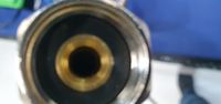
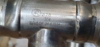
Range of stainless steel (SS304 or SS316L) press-fit fittings incorporating EPDM ‘O’-rings for use with *‐KJ600304 and *-KJ600316 stainless steel pipes. The "KJ6278" prefix models also incorporates an EPDM gasket on the union nut. Jointing is achieved via a crimping tool using a ‘M’ profile. For above and below ground use. Maximum working pressure 16.0 bar. Maximum operating temperature 85°C.
‘Numepress’ range of stainless-steel crimp fittings incorporating EPDM and ‘O’-rings for use with 'Numepress' stainless steel pipe. Connection is achieved via M profile press jaws. For above ground use only. Maximum working pressure 16.0 bar. Maximum operating temperature 95°C.
Fastwarm range of M type press copper crimp fittings with EPDM ‘O’-rings for use with copper tube manufactured to EN 1057. The joints are achieved by means of a crimping tool. For above ground use. Maximum working pressure: 16.0 bar. Maximum operating temperature: 85°C
‘Fastwarm’ range of U profile press fittings (nickel plated brass bodies) for use with ‘Fastwarm’ range of PERT/AL/PERT multi-layered pipes. Maximum working pressure 10.0 bar. Maximum operating temperature 95°C.
Range of brass compression fittings for use with copper pipes (manufactured to EN 1057). For above ground use only. Maximum working pressure 16.0 bar. Maximum operating temperature 85°C.
Range of ‘M’ profile copper press fittings with EPDM ‘O’-rings for use with copper pipes (manufactured to EN 1057). Jointing is achieved via a crimping tool using a ‘M’ profile. For above and below ground use. Maximum working pressure 20.0 bar. Maximum operating temperature 85°C.
Page 60 of 64
We use cookies to give you the best possible experience with WRAS. Some are essential to provide website functions and ensure the website is secure. We also use cookies to help us understand how people use the site and to make improvements. Click "Accept All" to enable recommended settings or click "Manage cookies" to adjust your settings. For more details, see our Cookie Policy.